Quantcast
Channel: Mechanical Engineering Projects,Seminar,Basic Notes
Viewing all 340 articles
Browse latest View live

COMBINATION OF PEDAL–POWERED HACKSAW,CHARGER AND WASHING MACHINE

$
0
0

COMBINATION OF PEDAL–POWERED HACKSAW ,CHARGER  AND WASHING MACHINE

Introduction
The power hacksaw machine, which runs on electric power, works on the principle of the conversion of rotational motion to oscillatory motion. The bicycle also uses the same principle. To give shape to his idea,  firstly buy an old bicycle from a scrap market, then cut the pedals of the bicycle from 12 cm to 8 cm and welded it as per requirement and re-affixed the pedals to it. 
 To use a guide to control the hacksaw blade which is used to cut the metal. Metal slabs were fitted on the hacksaw blade to ensure pressure on the object to be cut and linear movement of the blade. A clamp, with 360 degree rotation, was fixed to hold the metal pieces while cutting, and to allow them to be cut in any shape and angle.
Since a lot of energy is produced during the pedaling process, we will envision utilising it productively. We will fix a dynamo and a 12-volt battery to store the energy. To transfer the energy generated from dynamo to the battery, a forward-biased diode will use. The saved energy can be use to light a 12-volt bulb, which comes in handy while working in the dark.
Since a lot of energy is produced during the pedaling process, we will envision utilizing it productively. We will use the rotation of the cycle to rotate the attached bucket (PEDAL POWERED WASHING MACHINE).
Pedal operated Hacksaw And Charger


MATERIAL REQUIRED IN THE PROJECT

1)SCRAP  COMPONENTS OF BICYCLE
2)ALUMINIUM STRIP 
3)SQUARE TUBE
4)HACK SAW
5)NUT BOLT 
6)DYNAMO
7)BATTERY
8)PLYWOOD
9)POWER SUPPLY BLOCK
COMBINATION OF PEDAL–POWERED HACKSAW,CHARGER  AND WASHING MACHINE
COMBINATION OF PEDAL–POWERED HACKSAW,CHARGER  AND WASHING MACHINE
THIS PROJECT  IS  BASED ON THE ROTATIONAL MOVEMENT AND A LOT OF MECHANISM AND CHAIN SYSTEM
PEDAL MECHANISM
DYNAMO MECHANISM
BATTERY CHARGING SYSTEM
PEDAL WHEEL AND SPROCKET SYSTEM
CHAIN SYSTEM
DESIGN OF THE CHESIS OF CYCLE
DESIGN OF THE BUCKET 
WHOLE ROTATIONAL MECHANISM OF WASHING MACHINE

Working Of Project : 
  1.  PEDAL ROTATION BY THE HUMAN EFFORT
  2. QUICK RETURN CRANK SLOTTED MECHANISM WILL RECIPROCATE THE HACKSAW BY THE CHAIN SYSTEM 
  3. SPROCKET WILL ROTATE AND IT WILL ROTATE THE DYNAMO
  4. DYNAMO WILL ROTATE AND IT WILL CHARGE THE BATTERY WITH THE HELP OF FORWARD BASED DIODE
  5. 12 V CHARGED BATTERY WIlL USE IN THE LIGHTING THE LED BULBS AND TO CHARGE THE MOBILE
  6. BY THE CHAIN SYSTEM PROVIDE THE ROTATION TO THE WASHING BUCKET AND WE WILL GET THE WASHED CLOTHES
APPLICATION

METAL CUTTING IS DONE IN SMALL SCALES
WE CAN USE IT AT CONSTRUCTION SITES AND FURNITURE UNITS
TO CUT METAL FOR WINDOW PANES
CAN ALSO BE USED IN COLLEGE WORKSHOPS AND AUTO GARAGES TO SAVE ELECTRICITY
IT  CAN USE TO  WASH THE CLOTH
THIS WHOLE ARRANGEMENT WILL BE USED AS A EXERCISE EQUIPMENT
TO CHARGE THE MOBILE AND TO LIGHT THE 12V  LED BULB


Design and fabrication of drill tool dynamometer

$
0
0

Design and fabrication of drill tool dynamometer-Mechanical Project 


Introduction:
Dynamometers are devices used to measure cutting forces in machining operation. The cutting force cannot be detected or quantified directly but their effect can be sensed using Transducer. For example, a force which can neither be seen nor be gripped but can be detected and also quantified respectively by its effect and the amount of those effects (on some material) like elastic deflection, deformation, pressure, strain etc.
These effects, called signals, often need proper conditioning for easy, accurate and reliable detection and measurement. In other words, 
drilliing dynamometer project
Design and fabrication of drill tool dynamometer

Measurement involves three stages
  • Conversion into another suitable variable (deflection, expansion etc)
  • Amplification, filtration and stabilization
  • Reading or recording
Measurement of cutting force(s) is based on three basic principles:
  • measurement of elastic deflection of a body subjected to the cutting force
  • measurement of elastic deformation, i.e. strain induced by the force
  • measurement of pressure developed in a medium by the force.
Requirement of a cutting force dynamometer
  1. The dynamometer should have sufficient mechanical rigidity to avoid excessive deformation of the cutting edge under the action of cutting forces
  2. It should have sufficient sensitivity to enable measurement of cutting forces with sufficient accuracy
  3. It should have high stiffness and low mass, ensuring 100 percent transmissibility of force by its very high natural frequency. This feature will also enable the recorded force to be unaffected by the exciting vibration due to machining process itself. Example : milling , grinding and shaping
  4. It should be capable of indicating individual force components without any cross effect, while measuring such forces simultaneously
  5. The measuring system should be stable with reference to time, temperature and humidity, requiring only occasional checking after calibration.
Drilling dynamometer
Physical construction of a strain gauge type 2 – D drilling dynamometer for measuring torque and thrust force is typically shown schematically in Fig.and pictorially in Fig.. Four strain gauges are mounted on the upper and lower surfaces of the two opposite ribs for PX – channel and four on the side surfaces of the other two ribs for the torque channel. Before use, the dynamometer must be calibrated to enable determination of the actual values of T and PX from the voltage values or reading taken in SMB or PC.
Schematic view of construction of a strain gauge type drillin dynamometer.
Schematic view of construction of a strain gauge type drilling dynammometer 
Increasing deflection, δ enhances sensitivity of the dynamometer but may affect machining accuracy where large value of δ is restricted, the cutting forces are suitably measured by using the change in strain caused by the force.

The strain, ε induced by the force changes the electrical resistance, R, of the strain gauges which are firmly pasted on the surface of the tool-holding beam as

Gauge Factor = (Change in resistance /original resistance )

Force Measurement by strain gauge based Transducer
Force Measurement by strain gauge based Transducer  
The gauge connections may be
• full bridge (all 4 gauges alive) – giving full sensitivity
• half bridge (only 2 gauges alive) – half sensitive
• quarter bridge (only 1 gauge alive) –1/4 th sensitivity

Design and Fabrication of a Universal Coupling (Hooke's Joint ) Report Download

$
0
0

Design and Fabrication of a Universal Coupling (Hooke's Joint ) Report Download 

Abstract
A coupling is a device used to connect two shafts together at their ends for the purpose of transmitting power. The primary purpose of couplings is to join two pieces of rotating equipment while permitting some degree of misalignment or end movement or both.
A Universal coupling is a special type of coupling in which misalignment of shafts is allowed.
Shafts are free to move any direction in order to transmit torque or power from one shaft to another.
In this project work a Universal coupling was designed, in which safe torque on shafts and pin size of cross determined.
Finally the Universal coupling made by Mild Steel, which is low cost and available in every
workshop.

Introduction:
Couplings are mechanical elements that ‘couples’ two drive elements which enables motion to be transferred from one element to another. The drive elements are normally shafts. We tend to see lot of applications of the couplings mainly in the automobiles, for example the drive shaft which connects the engine and the rear axle in a bus or any automobile is connected by means of a universal joint.

The primary purpose of couplings is to join two pieces of rotating equipment while permitting some degree of misalignment or end movement or both. By careful selection, installation and maintenance of couplings, substantial savings can be made in reduced maintenance costs and downtime.

There are various types of coupling based on area of application and misalignment or degree of freedom to move in any direction. Such as the universal coupling allows the shafts to move in any directions. 

Universal Coupling or Hooke’s coupling:
A universal joint, (universal coupling, U-joint, Cardan joint, Hardy-Spicer joint, or Hooke's joint) is a joint or coupling that allows the shafts to 'bend' in any direction, and is commonly used in shafts that transmit rotary motion. It consists of a pair of hinges located close together, oriented at 90° to each other, connected by a cross shaft. The universal joint is not a constant velocity joint.
Basic of Universal Joint
Basic of Universal Joint 
A universal joint is like a ball and socket joint that constrains an extra degree of rotational freedom. Given axis 1 on body 1, and axis 2 on body 2 that is perpendicular to axis 1, it keeps them perpendicular. In other words, rotation of the two bodies about the direction perpendicular to the two axes will be equal.
In the picture, the two bodies are joined together by a cross. Axis 1 is attached to body 1, and axis 2 is attached to body 2. The cross keeps these axes at 90 degrees, so if you grab body 1 and twist it, body 2 will twist as well.
A Universal joint is equivalent to a hinge-2 joint where the hinge-2's axes are perpendicular to each other, and with a perfectly rigid connection in place of the suspension.
Universal joints show up in cars, where the engine causes a shaft, the drive shaft, to rotate along its own axis. At some point you'd like to change the direction of the shaft. The problem is, if you just bend the shaft, then the part after the bend won't rotate about its own axis. So if you cut it at the bend location and insert a universal joint, you can use the constraint to force the second shaft to rotate about the same angle as the first shaft.

Types of Universal coupling:

The universal couplings are categorized as-
i. Single joints
ii. Double joints
iii.Telescopic or assembled joints

Field of Applications of Universal Coupling:
Typical applications of universal joints include-
  1. AUTOMOBILE
  2. Aircraft
  3. Appliances
  4. Control mechanisms
  5. Electronics instruments
  6. Medical & optical devices
  7. Ordinance radio
  8. Sewing machines
  9. Textile machineries etc
Universal Coupling (Hooke's Joint )
Conclusion:
Mechanical design is a complex undertaking, requiring many skills. Design and fabrication of a Universal coupling was done in this project work. In designing problem safe torque on shaft was determined. The cross pin size (diameter) was determined considering bearing stress, shearing stress and bending stress taken into account. The application of a universal coupling also studied in this project work.

PNEUMATIC SHEET PUNCHING MACHINE MECHANICAL PROJECT

$
0
0

PNEUMATIC SHEET PUNCHING MACHINE

Synopsis
A pneumatic machine can be thought of as a large flexible mechanical structure that is moved by some sort of control system. The control system takes its input from a human operator and translates this command into the motion of actuators, which move the mechanical structure. The high performance and highly powerful, Pneumatic punching machine vice with the capacity for high volumes of punching has done.

Punching is a operation of producing permanent impression over a job, it historical day it is done by hammering, where nowadays it is done pneumatic machine with accessories
One form of inefficiency in current systems is due to the link between the flows of the two ports of the cylinder. This is because most valves use a single spool to control the flow in both ports. Because of this link, it is impossible to set the pressure levels in the two sides of the cylinder independently. 
Therefore, the outlet side will develop a backpressure, which acts in opposition to the direction of travel, which increases the pressure required on the inlet side to maintain motion. Since the force generated by the actuator is proportional to the pressure difference between the two sides, the actual pressures in the cylinder don't affect the action of the cylinder.

Generally, Pneumatic cylinder operations are based on Pneumatic pump operation. Air is pumping to the Pneumatic cylinder by using Pneumatic pump system. It’s the manual operation.
Pneumatic Punching Machine
Pneumatic Punching Machine 
Advantages:
1)More efficient
2)Power can be easily transmission.
3)Less loss in transmission.
4)Very Easy Holding Process

DESIGN AND FABRICATION OF TOGGLE JACK FULL REPORT DOWNLOAD

$
0
0

DESIGN AND FABRICATION OF TOGGLE JACK REPORT DOWNLOAD 

ABSTRACT
Toggle jacks are simple mechanisms used to drive large loads short distances. The power screw design of a common Toggle jack reduces the amount of force required by the user to drive the mechanism. Most Toggle jacks are similar in design, consisting of four main members driven by a power screw. In this report, a unique design of a Toggle jack is proposed which is very easy to manufacture. Each member, including the power screw sleeves, is made of the common c-shape. This eliminates the need for machined power screw sleeves, which connect the four members and the power screw together. The manufacturability of the proposed Toggle jack lowers the cost of production.

See Also: 7 Hydraulic Jack Related Mechanical Projects Report Download

INTRODUCTION
The most basic Toggle jack design is truly engineering at its finest. With the power to magnify input forces, Toggle jacks allow us to raise vast loads using only a fraction of the force ordinarily needed. Our goal in this project is to design an efficient Toggle jack capable of raising a 10000N load. As a screw-driven mechanical system, the jack will be manually operated and have at least 7 inches under load. The design will be transportable and storable, have a removable crank handle, and operate with a factor of safety of n = 5 using standard mechanical design methods for all components. The design itself has gone through multiple stages of development. We have taken several possible failure modes into account and are confident that our design is efficient and safe.

Design Catia Model Of Toggle jack
Catia Model Of Toggle jack 
SPECIFICATION
The Toggle jack design, shown in Figure 1, consists of four main lifting members, eight connection members, a power screw. Members 1 to 8 are all primarily bar shapes with ideal pin connections. Members 10 and 12 both have additional details to account for the contact surfaces. The power screw is double threaded with a collar at the member 12 connection. All members are EN8(C40) steel.

Components used in the fabrication of Toggle Jack:-
a) Power Screw
b) Nuts
c) Top plate
d) Base plate
e) Links
f) Pins
g) Spanner

Power screw
A power screw is a drive used in machinery to convert a rotary motion into a linear motion for power transmission. It produces uniform motion and the design of the power screw may be such that. Either the screw or the nut is held at rest and the other member rotates as it moves axially. A typical example of this is a screw clamp. Either the screw or the nut rotates but does not move axially. A typical example for this is a press. Other applications of power screws are jack screws, lead screws of a lathe, screws for vices, presses etc. Power screw normally uses square threads but ACME or Buttress threads may also be used. Power screws should be designed for smooth and noiseless transmission of power with an ability to carry heavy loads with high efficiency.
DESIGN AND FABRICATION OF TOGGLE JACK

Conclusion :

Our proposed design is similar to common Toggle designs in some aspects, but also advantageous in others. Similar to others, our proposed design can safely raise a load of 10000N to the required heights with relative ease on the user. Unique to our design, however, is the manufacturability of our design, which is much simpler. Since only Bar-shapes are utilized, bulk material can be more efficiently purchased and used. Also, less machining is required since there are no complex sleeves for the power screw. Only simple attachments which can be welded on are proposed. Therefore, when compared to similar Toggle jack designs that perform equally as well, our proposed design is recommended for its manufacturability and lower cost with high efficiency.

Download Report:

DESIGN AND FABRICATION OF PORTABLE PNEUMATIC FUEL PUMP

$
0
0

DESIGN AND FABRICATION OF PORTABLE PNEUMATIC FUEL PUMP

ABSTRACT

This project“DESIGN AND FABRICATION OF PORTABLE PNEUMATIC FUEL PUMP” is an outcome of basic instinct to increase the discharge rate and decrease the time of pumping the fuel from storage barrels to the machine or equipment especially industries where machineries are placed in second or third floor.
By utilizing simple pneumatic mechanism, fuel can be pumped especially with less power consumption and minimum human labour. When compared to traditional fuel pumping the time taken is also dramatically reduced, as the discharge rate is increased drastically.
Added advantage in this is portable and occupies less space. It is ideal for fuel pumping, as no electric field around the fuel pumping area.
This project is of great use to companies where pumping of fuel is everyday duty, even this project can be used in ration shops.

PROJECT OVERVIEW
In the pursuit of excellence, the manufacturing industries are seeking now in a new technology to improve productivity, quality of the product and reduce product cost. The cited subjects are seriously discussed in these days.
Most of the manufacturing industries use centrifugal pumps for pumping fuel from barrels to the required location. The discharge rate of centrifugal pump is low. The discharge head has also some limitations which restrict the use of centrifugal pump where high head is required.
As a fuel pump, the centrifugal pump is always risky because of electric motor placed just behind the impeller, which may lead to fire accidents.
Hence having this in mind, usage of reciprocating pump instead of centrifugal pump looked like the best alternate. Rather than keeping the idea in mind we brought it to reality. We tested the performance of both the pumps.
In this work a double acting reciprocating pump is used as fuel pump.

 PARTS OF THE FUEL PUMP

The following are the parts of the fuel pump,
  1. Pressure gauge
  2. Air adjustment screw
  3. Cylinder
  4. Suction pipe
  5. Filter
  6. Air hose
  7. Locknut
  8. Grease nipple
  9. 1/4 inch gate valve
  10. O Rings
  11. Cylinder head
  12. Tube couplers
DESIGN AND FABRICATION OF PORTABLE PNEUMATIC FUEL PUMP
WORKING PRINCIPLE
Initially starting with air compresses, its function is to compress air from a low inlet pressure (usually atmospheric) to a higher pressure level.  This is an accomplished by reducing the volume of the air.
Air compressors are generally positive displacement units and are either of the reciprocating piston type or the rotary screw or rotary vane types.  The air compressor used here is a typically small sized, two-stage compressor unit.  It also consists of a compressed air tank, electric rotor and pulley drive, pressure controls and instruments for quick hook up and use.  The compressor is driver by a 10HP motor and designed to operate in 145 – 175 PSI range.  If the pressure exceeds the designed pressure of the receiver a release value provided releases the excesses air and thus stays a head of any hazards to take place.
The stored air from compressor is passed through an air fitter where the compressed air is filtered from the fine dust particles.  However, before the suction of air into compressor a filter process take place, but not sufficient to operate in the circuit here the filter is used.
Then having a pressure regulator where the desired pressure to the operated is set.  Here a variable pressure regulator is adopted.
Through a variety of direction control value are available, a hand operated solenoid Valve with control unit is applied.
The solenoid valve used here is 5 ports, 3 positions.  There are two exhaust ports, two outlet ports and one inlet port.  In two extreme positions only the directions can be changed while the Centro ore is a neutral position and no physical changes are incurred.
The 2 outlet ports are connected to an actuator (Cylinder).  The pneumatic activates is a double acting, single rod cylinder.  The cylinder output is coupled to further purpose.  The piston end has an air horning effect to prevent sudden thrust at extreme ends.

ADVANTAGES
Even if all the other pumps are similar in use the Pneumatic water pump is more advantageous than the other pumps.
1.This is of compact in size
2.Less Maintenance is enough
3.The oil or water pumped is of higher pressure
4.Quite running and smooth operation is achieved.
5.Higher efficiency
6.Full efficient positive displacement pump
7.Effective working principle
8.It does not have any Prime mover, like electric motor related to the unit.
9.As the air is freely available, we can utilize the air to pumping the water and hence it is economical.
10. Less Maintenance

LIMITATIONS
1.It is costlier than the other types of pump because of compressor unit.
2.Less efficiency when compressed to other device.
3.Leakage of air affects the working of the unit.

DESIGN AND FABRICATION OF PNEUMATIC DRILL JIG FOR REDUCING LEAD TIME

$
0
0

DESIGN AND FABRICATION OF PNEUMATIC DRILL JIG FOR REDUCING LEAD TIME

ABSTRACT
      Our project is based on the need for the work holding devices. This design and fabrication which will enable the operation like drilling, reaming, tapping process easier. Our project is mainly composed of design and fabrication of the“PNEUMATIC DRILL JIG” which cover the absolute design to the specified dimensions of the work piece. This box jig is economical means to produce   
This pneumatic drill jig is provided with pneumatic clamping arrangement. This type of clamping arrangement saves the setting time, marking time, punching time etc. when compressed air is taken from a convenient medium to provide pope clamping force and good gripping to the component. As the quantity to produce is large the proposed pneumatic drill jig fulfills the mass production requirement in the shop. Clamping can be done by releasing the pressured air using valves.

The component is placed in between the Jig plate and the locator, which is on the piston rod. When the valve is opened, the compressed air from the compressor will enter into the cylinder through a hole at the bottom of the cylinder. The piston inside the cylinder is made to push in the upward direction. When the piston moves the locator clamps the component rigidly. Now the component is ready for drilling operation.

When the two-way valve is closed the piston will return to bottom position to release the clamps. When we close the valve, the piston will come in very high force in downward direction. So these are chances for the damage of piston. To avoid this, we are using FLOW CONTROL VALVE to control the flow of piston. This can be repeated with the same procedure as described above.
DESIGN AND FABRICATION OF PNEUMATIC DRILL JIG FOR REDUCING LEAD TIME
ADVANTAGES:
  1. It eliminates the individual marking, positioning and frequent checking.
  2. The operation time is reduced due to increase in speed, feed and depth of cut because of high clamping rigidity.
  3. It is very much useful in mass production.
  4. It makes possible to employ unskilled or semi skilled operator to make savings in labor cost.
  5. It partially automates the tools.
  6. It reduces the expenditures on quality control of machine parts.   
LIMITATIONS:
  • It is only used for small size components.
  • Forces causing deflection may come from handling

Multipurpose coconut, mango, sugar cane bud cracker machine

$
0
0

Multipurpose coconut, mango, sugar cane bud cracker machine

Introduction
  • In this project we are performing the multipurpose operations like coconut, mango and sugar cane bud cracker machine.
  • In this project we are fabricate the hand operated multipurpose operations like coconut, mango and sugar cane bud cracker machine. This equipment needs no electrical power to operate, just using the manual power to handle. This project reduces the cost involved in concern and also avoids the electrical power usage. This project is very useful for small scale industries and domestic purpose.
  • Now the project mainly concentrates on designing a suitable operating system. To maintain simplicity and economy in the design the locally fabricated unit has been used.
  • Our project achieves higher safety, reduces human effort, increases the efficiency, reduces the work load, reduces the fatigue of workers and reduces maintenance cost.
Objective of the project
  1. To understand the basic principal of the our project
  2. Describe the construction and working of various parts of our project
  3. Development of the working model of the our project
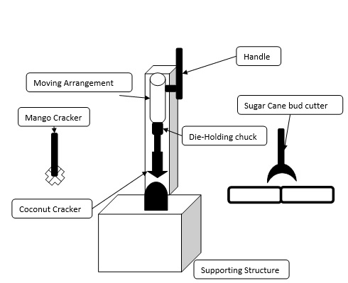
Main parts used in project
  1. Mango cracker Die
  2. Coconut Cracker Die
  3. Sugar Cane bud Cutting Die
  4. Handle 
  5. Supporting Structure
  6. Holding Chuck
Block diagram of projects:
Multipurpose coconut, mango, sugar cane bud cracker machine

Working of the project
The base contains the all parts of this equipment. The supporting arm is fixed on the base, in the supporting arm pivot; handle and moving arrangements are fixed. The end of the moving arrangement the die is fixed. The coconut, mango and sugar cane bud are fixed below the male die in the base. We material placed below male die and then press the handle. The handle comes down then the pivot is pressing the moving arrangement, then the moving arrangement with male die comes down. During this movement the male coconut, mango and sugar cane bud crack at a required shape for our need.. This equipment is easily operated able to less skilled labors also. So this equipment is suitable for small scale industries and domestic purpose.

Advantages
  1. No conventional grid electricity required
  2. Long operating life
  3. Highly reliable and durable
  4. Easy to operate and maintain
  5. Eco-friendly
  6. No fuel cost
Dis-advantages
  1. High installation cost
  2. Depending upon availability.

Pneumatic Material Handling System Mechanical Project

$
0
0

Pneumatic Material Handling System Mechanical Project 

INTRODUCTION

Various types of pneumatic lifting and lowering devices are used to lift and move, and operate items and to perform work operations. Farm style tractors have incorporated the use of the three point hitch style lifting mechanism for many years, due to their controllable on board hydraulic systems, that provides the power of motion for the lifting mechanism and movement of the lifting arms. This new invention, the portable pneumatic lifting and lowering device, as example, now enables the user to quickly and easily attach it to their vehicle's trailer hitch receiver port and then hook up the electrical, air or hydraulic power source to the power of motion mechanism on the portable pneumatic lifting and lowering device, and under user controlled mechanism(s), enabling the user to operate the pneumatic lifting arms of the device to lift and lower various items

OBJECTIVE
  1. Understanding the Construction and working of various parts in pneumatic material handling system
  2. Fabrication of demonstration model of in pneumatic material handling system
BLOCK DIAGRAM
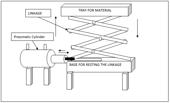
Main Parts used in pneumatic material handling system
a)Tray
b)Mechanical Linkage
c)Pneumatic cylinder mechanism
Pneumatic Material Handling System Mechanical Project
Pneumatic Material Handling System Mechanical Project 
ADVANTAGES
  1. It requires simple maintenance cares
  2. The loaded light load can be easily.
  3. Checking and cleaning are easy, because of the main parts are screwed.
  4. Handling is easy.
  5. Manual power required
  6. Repairing is easy.
  7. Replacement of parts is easy

DESIGN AND FABRICATION OF EQUALISER CLAMP

$
0
0

DESIGN AND FABRICATION OF EQUALISER CLAMP


ABSTRACT

“Time is very essential for every one” so we are pleased to design and fabricate a project on clamping device namely“EQUALISER CLAMP” which saves the time while clamping the work piece and makes the machining very easy and accurate.

Our project hold the work piece securely in correct position while machining it with the help of our project machining operations like Drilling, reaming, tapping, shaping etc and various machining operations can be performed easily.

 Objectives of our project are:
  • It is used for clamping two unequal workpiece simultaneously.
  • It will hold the work piece rigidly against all disturbing forces.
  • Clamping force should be equally distributed to all the workpieces.
  • Skilled labours are not required.
  • High accuracy can be maintained.
  • Time consumption is very less for clamping and machining.
  • Economically more advantage
DESIGN AND FABRICATION OF EQUALISER CLAMP
EQUALISER CLAMP
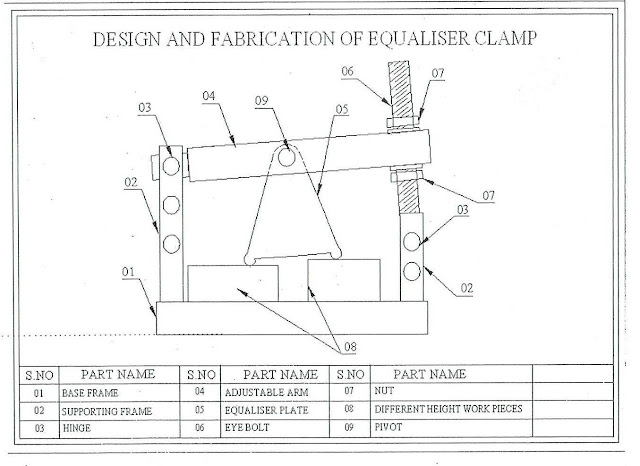
  • In multiple clamping, a pivoted equalizer is used for clamping two unequal workpiece simultaneously.
  • The equalizer clamp pivots around the pin to suit the workpiece.
  • Equalizer principle can be extended to facilitate clamping of many even number of work pieces simultaneously by a single clamp.
  • The main advantage of this type of clamp is that clamping force is equally distributed to all work pieces.
DESIGN AND FABRICATION OF EQUALISER CLAMP
EQUALISER CLAMP

What Is Honing Machine Process used For Super Surface Finishing

$
0
0

What Is Honing Machine Process used For Super Surface Finishing 

Honing is a finishing process, in which a tool called hone carries out a combined rotary and reciprocating motion while the workpiece does not perform any working motion. Most honing is done on internal cylindrical surface, such as automobile cylindrical walls. The honing stones are held against the workpiece with controlled light pressure. The honing head is not guided externally but, instead, floats in the hole, being guided by the work surface . It is desired that

1. honing stones should not leave the work surface
2. stroke length must cover the entire work length.

In honing rotary and oscillatory motions are combined to produce a cross hatched lay pattern as illustrated in Fig

Honing tools and Honing Operations
Honing tools and Honing Operations 
Honing is an operation that is used primarily to improve the surface finish of holes produced by processes such as boring, drilling, and internal grinding.

The honing tool consists of a set of aluminum oxide or silicon-carbide bonded abrasive sticks, usually called stones (Fig. ). They are mounted on a mandrel that rotates in the hole at surface speeds of 45 to 90 m/min, applying a radial force. The tool has a reciprocating axial motion, which produces a crosshatched pattern on the surface of the hole.

The stones can be adjusted radially for different hole sizes. Oil- or water-based honing fluids generally are used to help flush away the debris. Honing is also done on external cylindrical or flat surfaces and to manually remove sharp edges on cutting tools and inserts.

The quality of the surface finish produced by honing can be controlled by the type and size of abrasive used, the pressure applied, and speed. A fluid is used to remove chips and to keep temperatures low. If not performed properly, honing can produce holes that are neither straight nor cylindrical, but rather in shapes that are bell mouthed, wavy, barrel shaped, or tapered.

The honing stones are given a complex motion so as to prevent every single grit from repeating its path over the work surface. The critical process parameters are:
1. rotation speed
2. oscillation speed
3. length and position of the stroke
4. honing stick pressure
With conventional abrasive honing stick, several strokes are necessary to obtain the desired finish on the work piece. However, with introduction of high performance diamond and cBN grits it is now possible to perform the honing operation in just one complete stroke. Advent of precisely engineered microcrystalline cBN grit has enhanced the capability further. Honing stick with microcrystalline cBN grit can maintain sharp cutting condition with consistent results over long duration.

Advantages
  • The workpiece need not be rotated by power, there are no chucks, faceplates, or rotating tables needed, so there are no chucking or locating errors. 
  • The hone is driven from a central shaft, so bending of the shaft cannot cause tapered holes as it does when boring. 
    The result is a truly round hole, with no taper or high or low spots, provided that the previous operations left enough stock so that the hone can clean up all the irregularities.
  • Honing uses a large contact area at slow speed compared with grinding or fine boring, which use a small contact area at high speed. Because of the combined rotating and reciprocating motion used, a crosshatched pattern is created which is excellent for holding lubrication. Diameters with 0.001 to 0.0001 inch and closer accuracies can be honed by using diamond stones similar to diamond wheels.
Limitations: 
  1. Honing is though of as a slow process. However, new machines and stones have shortened hone times considerably. 
  2. Horizontal honing may create oval holes unless the work is rotated or supported. If the workpiece is thin, even hand pressure may cause a slightly oval hole.

Design and Fabrication Of Gear cutting attachment on lathe machine report

$
0
0

Design and Fabrication Of Gear cutting attachment on lathe machine report Download 

PROBLEM STATEMENT

Lathe is suitable for operations like turning, boring, facing taper turning, thread cutting, knurling, etc. but not suitable for operations like key way cutting etc. Because in a conventional lathe as soon as the machine is switched on, the workpiece fixed to the chuck rotates. This is a major limitation of the conventional lathe keeping in view of the present project work.

Gear cutting is a specialized form of milling, and the lathe is quite suited to this job for smaller work (6" diameter or so) with the help of attachment.


OBJECTIVE

The objective of this project is:
  • Our project design and fabrication of gear cutting attachment is used to cut gear or splines over the cylindrical job.
  • Our main aim is to prove lathe as a versatile machine and with the help of gear cutting attachment the object is possible by lathe itself.
Cutting of a Spur Gear on a Milling Machine involves the following steps:
1.To determine the important dimensions and proportions of the gear tooth
element.
2.Mounting the cutter and the job on the machine.
3.Adjust the position of the table to the starting position.
4.Indexing.
5.Repeat the operation till the gear is complete.

Design and Fabrication Of Gear cutting attachment on lathe machine report
Design and Fabrication Of Gear cutting attachment on lathe machine  
INDEXING
Indexing is an operation of dividing the periphery of a piece of work into any number of equal parts, for e.g. this operation can be adopted for producing hexagonal and square headed bolts, cutting spines on shafts, fluting drills and in gear cutting. All these works require a holding device which will permit the rotation of the work about the axis so that periphery of the work piece can be divided equally and accurately. Such a work holding devices is known as DIVIDING HEAD OR INDEXING HEAD.

ANALYSIS OF DESIGN
Final parts and final assembly is analyzed by solid works software. We use parameters of standard lathe machine and milling cutter for force analysis.The analysis was done on the basis of –
Static force
Maximum principal elastic strain
Maximum shear stress
Von Mises elastic strain
Von Mises stress
Factor of safety

Design and Fabrication Of Gear cutting attachment on lathe machine-ansys model
Download:

DESIGN AND FABRICATION OF SHEET ROLLING MACHINE

$
0
0

DESIGN AND FABRICATION OF SHEET ROLLING MACHINE

ABSTRACT
This project work titled “SHEET ROLLING MACHINE” has been conceived having studied the difficulties in making bending in sheet metal. This project facilitates in making bending accurate in sheet metal with easy. The project employee by using the roller for bending purpose by manual.
This machine can be used in various fields. Our project the sheet metal rolling is very simple in operation by using roller which is coupled with handle.

In Sheet Metal working industry a wide range of power and hand operated machines are used. This machine is simple in construction and working.

Introduction :
Our project the“SHEET METAL ROLLING MACHINE” finds huge application in Sheet Metal industry. Rolling is the process of bending sheets to a curved form. The article in the shape of cylinders is made by rolling roller.
Rolling operation can be done on hand or power operated rolling machines. In forming cylindrical shapes a gradual curve is to be put in the metal rather than sharp bends. The gap between the rollers can be regulated by hand operated screws.

Sheet metal is available in flat pieces or as a coiled strip. Various forming process in sheet metal include:
  1. Punching
  2. Roll forming
  3. Rolling
  4. Spinning
  5. Stamping
  6. Bending
  7. Deep drawing
  8. Expanding
  9. Curling
  10. Press brake forming
  11. Decambering
  12. Ironing
  13.  Laser cutting
  14.  Incremental sheet forming etc.
Sheet Rolling machine mechanical project
Sheet Rolling machine 
Roll bending
A continuous form from of three-point bending is roll bending, where plates, sheet and rolled on each end, one of the support can often be swung clear to permit the removal of closed shapes from the rolls shapes can be bent to a desired curvature on forming rolls. These machines usually have three roll in the of a pyramid, with the two lower rolls being driven and the position of the upper roll being adjustable by a frame.

DESCRIPTION OF THE MACHINE

The Sheet Metal Rolling Machine works according to the principle of three point bending. The rotation of the driven rolls being utilized to feed the metal through the rolls by means of the frictional forces present between the surface of the rolls and sheet. No lubricant is used at its presence interference with the ability to grip. Sheet Metal Rolling Machine essentially consists of three rollers, used to manufacture circular components like cylinders. Sheet Metal Rolling Machine is classified into two types based on the arrangement of the rollers. 

They are as follows.
1. Pinch type machine
2. Pyramidal type machine

This machine is of pinch type here only the top roll serves as a driven, bottom roller are idler and rotates on friction with the work metal blank.

WORKING PRINCIPLE
The Sheet Metal, which is to be formed in cylindrical shape, is present atm the edge by hammering. To start the operation easily and to avoid flats at the beginning and at the ends of the rolled form. In rolling cylindrical shapes a gradual curve is to be put in the metal rather than sharp bends. Now the sheet metal is introduced between the top and the bottom rolls, the gap between the top and bottom rolls are adjusted as per the required diameter by regulating the screw rods.

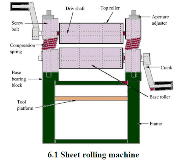
The rollers were arranged in triangular form; two sets of rollers below and one above. The upper roller provide the bending force while the back base roller provides the required driving force and the front end Roller bends the metal according to set radius of bend. Aperture adjuster on each block assembly ensure loading of workpiece and adjustment to required radius of bent. The free end of the top bearing block is spring loaded to increase or to reduce top-base roller clearance. Two other bores on each bearing blocks provide an adjustment for the roller gap variability. Top roller Provides the bearing load (bending force)and also compliments the driving roller when working on thick materials.
 The lower back roller provides the necessary driving forces while the idler roller does the bending and material delivery. There are two crank levers, one on the top roller and another on the front end
roller. The lever (handle) coupling head has a square configuration which fits into the square end of the roller shaft.
The frame structure made of(50×50×5)mm angle iron for the purposes of strength. The tool table is provided below the rollers for safe keeping of tools and cranks. The roller head assembly is detachable from the frame and can be mounted on a table to be used as a table top machine for tinkering works.

ADVANTAGES
  • Operation of this machine is very simple
  • Unit is compact so less space is required
  • No hand tools are required
  • Cylindrical shaped objects of dia. 50 mm to 225 mm can be produced
  • The diameter can be easily operate this machine
  • The machine is hand operated. So the cost of the finished product will be less.
  • The total cost of the machine is less.
  • Maintenance of this machine is very easy.
  • Easy to handle
  • Less effort and productive
  • Easy to install at any were
  • Skilled workers are not required
  • Convenient for mass production
  • Less in weight
DISADVANTAGES
  • This machine has a hand operated one
  •  Production time is high.
APPLICATIONS
Sheet Metal rolling machine is used to make,
  1. Outer cylindrical casing for motors employed in submersible pumps.
  2. Hydraulic and pneumatic cylinders
  3. Bodies of shells and condensers
  4. Dairy equipment
  5. Compressors storage tanks etc…
  6. It is also used to make cylinders of different diameters
Download

DESIGN AND FABRICATION OF PNEUMATIC LIFTING TABLE

$
0
0

DESIGN AND FABRICATION OF PNEUMATIC LIFTING TABLE

ABSTRACT 

This project is developed for the users to lift any weight using air pressure. High pressure air is stored in a tank. A cylinder with piston arrangement is connected with a zig-zag pattern. Two pipes connected with ball valves connect the air tank with the cylinder. When one valve is opened, the air rushes out into the cylinder. Therefore the piston moves in one direction.
The rod connected with the piston pushes the zig-zag frame so that the lift moves up. When the other ball valve is opened, the air inside the cylinder is released. Therefore the lift comes down.

Introduction:

A hydraulic fluid power system is defined as a means of power transmission in which relatively in compressible fluid is used as the power transmitting media. The primary  purpose of pneumatic system is the transfer of energy from one location to another location and this energy into useful work.
In this project of the fabricated model of will describe the working principles as well as hydraulic machines application and its advantages. Efforts have been taken to show the path of hydraulic fluid as it is applied and released. The system pressure can be generated in the form of any physical action which result a compression over the pneumatic pressure which is developed in the form of air compressing externally can be applied to activate system. There is a constant relation between pressure density, and volume, According to Bernoulli’s equation.
DESIGN AND FABRICATION OF PNEUMATIC LIFTING TABLE
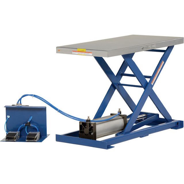
Source               DESIGN AND FABRICATION OF PNEUMATIC LIFTING TABLE
Lift tables are used to raise and position work pieces for ergonomic access. They are used for material positioning, load positioning, or lifting. This lifting has a pneumatic  power source and is safe for heavy paint applications and other hazardous locations. This lift comes with alternative power sources

CONSTRUCTION AND WORKING
This project is developed for the users to lift any weight using air pressure. High pressure air is stored in a tank. A cylinder with piston arrangement is connected with a zig-zag pattern. Two pipes connected with ball valves connect the air tank with the cylinder. When one valve is opened, the air rushes out into the cylinder. Therefore the piston moves in one direction. The rod connected with the piston pushes the zig-zag flame so that the lift moves up. When the other ball valve is opened, the air inside the cylinder is released. Therefore the lift comes down. The main objective of Zig-Zag Pneumatic Lift project is developing a lift system for lifting any weight using air pressure.

In this project, we stored high pressure air in a tank. A zig-zag pattern is connected with a cylinder with piston arrangement.
The cylinder and the air tank are connected by the two pipes with ball valves. When one ball valve is opened, the high pressure air will enter into the cylinder. Hence, the piston will move in one direction. The rod connected with the piston pushes the zig -zag frame so that the lift moves up. When we open the other ball valve, the air inside the cylinder is released. So, the lift comes down.

CONTINUOUS CUT-OFF MACHINE | Automation In Cut-off Machine Project

$
0
0

Low Cost Automation Sensor Based Continuous Cut-Off Machine  | Automation In Cut-off Machine Project 

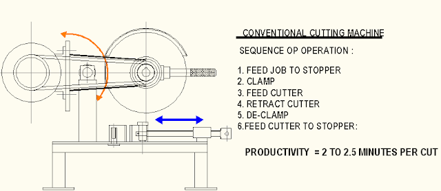
In the process of production of any components from steel bar stock , the preliminary process is that of cutting-off of bar stock to length according to the finished size requirements of work piece. This process is normally done by an power hacksaw machine.

The sequence of operation is as follows:
1.Feed bar stock to stopper that is set according to length of work piece to be cut.
2. Clamp the bar stock 
3. Feed the cutter blade to cut the required length. 
4, Retract the cutter
6. De-clamp the work piece
….procedure repeated.
Conventional Cut-off machine
Conventional Cut-off machine 
PROBLEM DEFINITION:
The above sequence if observed has the human intervention through out the process is necessary and more over the process of bar cutting does not add to the value of the product hence can be treated to be an idle time. Thus there is an attempt in the form of continuous cutting off machine to reduce the idle time to a minimal value. In the machine once the bar stock  is fed to the stopper the machine automatically feeds the cutter to the work piece until it is cut to the required length during the cutting stroke and during the return stroke the bar will automatically fed to the stopper by the machine itself , and so also the clamping of bar stock during cutting stroke and de-clamping being done by the machine itself.

SOLUTION
The solution to the above problem is the development of  a low cost automation based machine using a proximity sensor to sense the job feeding ( for semi-auto model feeding the job to length is manual) . ..further clamping , cutter feed , cutter retraction , de-clamp operations are automatic and fast …

CONTINUOUS CUT-OFF MACHINE | Automation In Cut-off Machine Project
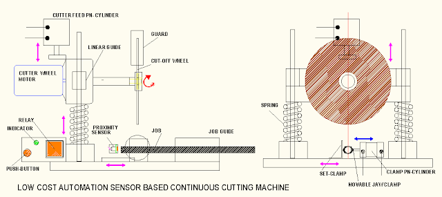
Low Cost Automation Sensor Based Continuous Cutting machine 
WORKING  :
The sequence of operation for the machine is as follows:
1. Feed job to length.
2.Proximity sensor senses the job,…..circuit is   ‘ON’
3. Clamp cylinder operates to clamp the job
4. Cutter feed cylinder operates to feed cutter in downward direction to cut the job….feed rate is adjusted using flow control valve.
5. Press ‘ PUSH BUTTON’----Sensor is by-passed …this makes circuit ‘OFF’
6. Clamp cylinder reverses stroke ---job is de-clamped
7. Cutter feed cylinder reverses …..return strokes are faster to save idle time.
8. Feed job again …..continue steps 1 to 7

CONSTRUCTIONAL FEATURES :

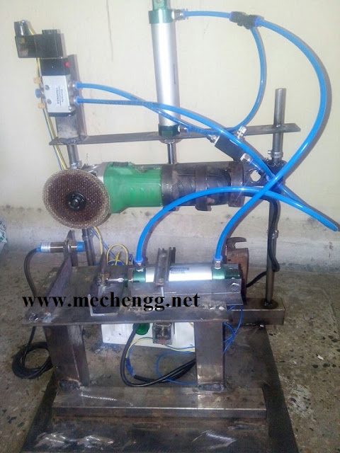
1. Cutter motor and cutter head : Cutter motor is 100 watt motor variable speed 0 to 8000 rpm ..with a standard 1:3 ratio gear head thus output speed of cutter will be 2600 to 0.

2. Linear slide and cutter feed arrangement: Linear slide comprises of two linear motion bearings on wither side with guide bars and set op helical compression springs. The feeding action is done by a double acting pneumatic cylinder ….speed of the piston in forward direction ie, the cutter feed is controlled flow gradual cutting action  using a flow control valve in circuit.,where as the return stroke is standard  ( fast action). Springs are provided for fast return of the cutter head to original position.

3. Job clamping and guide arrangement: Job is guided in the job guide where as the clamping is achieved using a set of clamps namely , the set- clamp ( adjustable to accommodate different size of job) ….where as the movable jaw is connected to another pneumatic cylinder which is operated in tandem to the cutter feed cylinder.

4. Job Feeding and sensing arrangement : For the semi-automatic version of the machine the feeding action is manual ie, the job is fed in the job guide manually upto stooper. , the proximity sensor is used to sense the job. The sensor then actuates the electrical circuit comprising of an electronic 8-pin relay and push button system..

5. Proximity sensor and electrical circuit 
Proximity sensor and the electronic relay circuit is a simple electrical circuit used to sequence the operations in the circuit , it can also be replaced by an limit switch arrangement….but sensor is more reliable ….the circuit decides the on/off of the 5/2 way direction control valve in the pneumatic circuit and thereby the clamping/cutting /return action.

6. Pneumatic circuit: 
Pneumatic circuit uses two double acting pneumatic cylinders , one 5/2 way direction control valve and one flow control valve., functions of the above components have already being explained above.

CONTINUOUS CUT-OFF MACHINE
CONTINUOUS CUT-OFF MACHINE 
ADVANTAGES

1.Job feeding upto stopper is sensor based ..so job size accurate. 
2.Clamping of bar stock during cutting stroke is automatic
3.De-clamping of bar stock after cutting stroke is automatic 
4.Job feeding takes place during return stoke of the machine there by reducing the idle time further.
5.Minimal human intervention only limited to replacing the bar stock on to the machine

APPLICATION

1.Job stock cutting in production of automobile and industrial components.
2.Conduit cutting for wire harnesses used in cars
3.PVC sleeve cutting used as insulating material in electrical machine.


Buy Project Model :

Contact Details :
Mr. Karan Borase
projectpark111@gmail.com
Mob No:9011003211

Automatic PVC pipe Cutting Machine Mechanical Project

$
0
0

Automatic PVC pipe Cutting Machine Mechanical Project 

Abstract:
• Cutting the tools or the materials of finite length by manually will not yield a good result.
• So we have designed and developed the system which will cut the material automatically of finite length according to our requirements.
• We mainly concentrate on PVC cutting Machine for which we have designed the system.

The IR sensor is placed on the PVC machine where the final output PVC comes out of the machine. The IR sensor senses the Length of the PVC and the corresponding length.
Automatic PVC pipe Cutting Machine Mechanical Project
Automatic PVC pipe Cutting Machine Mechanical Project 

APPLICATIONS
  1. This machine is very useful for small scale industries
  2. This machine is used to cut the roller sheet metal
  3. All Industrial Application
DISADVANTAGES
  •  High torque can not be obtained
  •  Load carrying capacity of this unit is not very high.(<50 font="" n="">50>
ADVANTAGES
  • Quick response is achieved
  • Simple in construction
  • Easy to maintain and repair
  • Cost of the unit is less when compared to other machine
  • No fire hazard problem due to over loading
  • Comparatively the operation cost is less
  • Continuous operation is possible without stopping
Conclusion
• According to the length what we design the cutting tool, cuts the PVC automatically.
• This type of cutting machine can be used anywhere, where we find the application of cutting the
materials of finite length automatically .
• it results in very accurate value. This is applicable to all type of industries.

Introduction Of Electro Hydraulic Forming (EHF) | Advantages And Application

$
0
0

Introduction Of Electro Hydraulic Forming | Advantages And Application 

Electro Hydraulic Forming is type of high energy rate forming processes

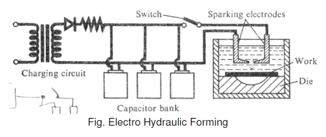
Electrohydraulic forming is a type of metal forming in which an electric arc discharge in liquid is used to convert electrical energy to mechanical energy and change the shape of the workpiece. A capacitor bank delivers a pulse of high current across two electrodes, which are positioned a short distance apart while submerged in a fluid (water or oil). The electric arc discharge rapidly vaporizes the surrounding fluid creating a shock wave. The workpiece, which is kept in contact with the fluid, is deformed into an evacuated die.

HIGH ENERGY RATE FORMING PROCESSES

       The parts are formed at a rapid rate, and thus these processes are also called high – velocity forming processes. There are several advantages of using these forming processes, like die costs are low, easy maintenance of tolerances, possibility of forming most metals, and material does not show spring-back effect. The production cost of components by such processes is low. The limitation of these processes is the need for skilled personnel.

          There are three main high energy rate forming processes: explosive forming, magnetic forming, and electro hydraulic forming. We shall discuss these processes.

Electro Hydraulic Forming

          Electro hydraulic forming (EHF), also known as electro spark forming, is a process in which electrical energy is converted into mechanical energy for the forming of metallic parts. A bank of capacitors is first charged to a high voltage and then discharged across a gap between two electrodes, causing explosions inside the hollow work piece, which is filled with some suitable medium, generally water. These explosions produce shock waves that travel radially in all directions at high velocity until they meet some obstruction. If the discharge energy is sufficiently high, the hollow work piece is deformed.
Electro Hydraulic Forming
Principle
  1. A sudden electrical discharge in the form of sparks is produced between electrodes and this discharge produces a shock wave in the water medium. This shock wave deforms the work plate and collapses it into the die.
  2. The characteristics of this process are similar to those of explosive forming. The major difference, however, is that a chemical explosive is replaced by a capacitor bank, which stores the electrical energy.
  3. The capacitor is charged through a charging circuit. When the switch is closed, a spark is produced between electrodes and a shock wave or pressure pulse is created. The energy released is much lesser than that released in explosive forming.
Process Characteristics:
i) Stand off distance: It must be optimum.
ii) Capacitor used: The energy of the pressure pulse depends on the size of capacitor.
iii) Transfer medium: Usually water is used.
iv) Vacuum: the die cavity must be evacuated to prevent adiabatic heating of the work due to a sudden compression of air.
v) Material properties with regard to the application of high rates of strain.

Limitations:
i) Suitable only for smaller works
ii) Need for vacuum makes the equipment more complicated.
iii) Proper SOD is necessary for effective process.

Advantages of EHF
  • A single-step process (rather than progressive stamping)
  • Fine details and sharp lines can be easily formed
  • Forming of male and female shapes (negative and positive)
  • Only a single one-sided die is required
  • Enables extremely deep forming (much more than is possible with conventional stamping)
  • Even distribution and higher strength of thin material
  • Extremely fast
  • Equipment has small footprint
  • No need for a press – the forming chamber is a self-balanced system
  • Allows forming of parts up to a few square meters in size.
Accuracy of parts produced

          Accuracy of electro hydraulically formed parts depends on the control of both the magnitude and location of energy discharges and on the dimensional accuracy of the dies used. With the modern equipment, it is now possible to precisely control the energy within specified limits, therefore the primary factor is the dimensional accuracy of the die. External dimensions on tubular parts are possible to achieve within ± 0.05 mm with the current state of technology.

Applications:

They include smaller radar dish, cone and other shapes in thinner and small works.
Example Of Electro Hydro Forming Components
Example Of Electro Hydro Forming Components 

PNEUMATIC POWER STEERING MECHANICAL PROJECT

$
0
0

PNEUMATIC POWER STEERING MECHANICAL PROJECT

Introduction

Power steering systems have contributed to reduced driver fatigue and made driving a more pleasant experience. Nearly all power steering systems at the present time use fluid pressure to assist the driver in turning the front wheels. Since driver effort required to turns the front wheels is reduced, driver fatigue is decreased. The advantages of power steering have been made available on many vehicles, and safety has been maintained in these systems.
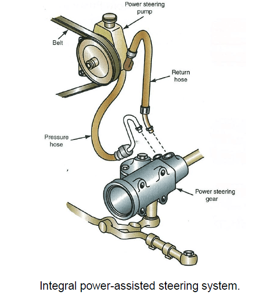
There are several different types of power steering systems, including integral, rack and pinion, hydroboost, and linkage type. In any of these systems, the power steering pump is the heart of the system because it supplies the necessary pressure to assist steering.
The power steering pump drive belt is a simple, but very important, component in the power steering system. A power steering pump in perfect condition will not produce the required pressure for steering assist if the drive belt is slipping.

Integral power-assisted steering system

In the integral power-assisted steering system, the pump is bolted to a bracket on the engine, and the recirculating ball steering gear is mounted on the frame beside the engine. This type of steering system is used on many rear-wheel-drive cars and light-duty trucks. The pump is driven by a belt from the crankshaft and an integral reservoir is mounted on the pump. A high-pressure hose and a return hose are connected from the pump to the steering gear
POWER STEERING
POWER STEERING 
Introduction
Pneumatic machinery are machines and tools which use air power to do work. Heavy equipment is a common example. In this type of machine, high pressure Compressed air is transmitted throughout the machine to various Pneumatic motors and Pneumatic cylinders. The air is controlled directly or automatically by control valves and distributed through hoses and tubes. 

Scope objective
The popularity of Pneumatic machinery is due to the very large amount of power that can be transferred through small tubes and flexible hoses, and the high power density and wide array of actuators that can make use of this power. These machinery are based on the Cylinders, Compressor and Pump.
Working 
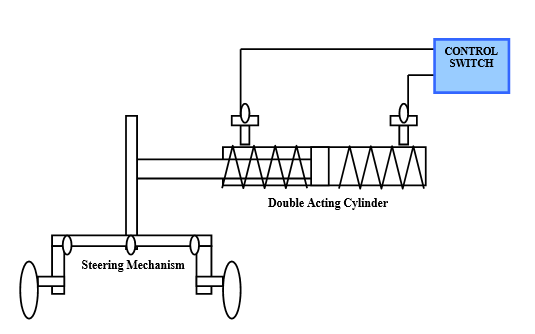
Pneumatic cylinders are pressurized by Pneumatic pressure and get their power for the Pneumatic air under pressure. They transform the air’s energy to linear work. A Pneumatic cylinders works in a Pneumatic system and is the motor side of this system. The generator side of the air Pneumatic system is the pump or Compressor that brings a fixed or regulated air flow into the system. The Pneumatic cylinder initiates the pressure of the air, which can never be larger than the pressure that is asked by the load. The cylinder consists of a cylinder barrel, in which a piston connected to a piston rod is moving. The barrel is closed by the cylinder bottom at the bottom side and by the cylinder head at the side where the piston rod comes out of the cylinder. Mounting bracket or clevises are mounted to the cylinder bottom as well as the piston rod. The piston has sliding rings and seals. The piston divides the inside of the cylinder in two chambers, the bottom chamber and the piston rod side chamber. 
PNEUMATIC POWER STEERING MECHANICAL PROJECT
PNEUMATIC POWER STEERING MECHANICAL PROJECT 
By pumping Pneumatic air to the bottom side of the Pneumatic cylinder, the piston rod starts moving out. The piston pushes the air in the other chamber back to the air reservoir. If we assume that the air pressure in the piston rod chamber is zero, the pressure in the cylinder is now Force/Piston area.
 If the air is pumped into the piston rod side chamber and the air from the piston area flows back to the air reservoir without pressure, the pressure in the piston rod area chamber is Load/(piston area - piston rod area). In such a way the Pneumatic cylinder can push and pull.
When the vehicle weight increases, the power required to steer the vehicle also increases. Most of the vehicles are have fluid power for steering.
In this project pneumatic power (compressed air) is used in place of Mechanical power.

Application
1.Used in all light duty vehicles like cars

Expected outcome
1.Very easy to drive vehicle than fluid power.
2.No moving parts.
3.Easy maintenance.
4.No separate drive is required to drive the compressor as the brake system has the compressed air for operation.

Subject wise R K Kanodia GATE Mechanical Books Download

$
0
0

Subject wise R K Kanodia GATE Mechanical Books Download 

Hello Friends
This Blog contains all the information about Gate Mechanical from Preparation to Admission into PSU/IIT. I am writing this blog because of lack of information about GATE Exam pattern for students especially currently pursuing their Engineering Degree. Many Students do not able to score much high because of lack of its information.

R K Kanodia Books are considered as best book for gate preparation among all Gate Mechanical Engineering books. G.k. Publication Books are also good but the book has lots of mistakes so I suggest you to go with Kanodia mechanical Gate book.

See Also : Gate Mechanical R K Kanodia Preparation Material and Notes

Subject wise R K Kanodia GATE Mechanical Books Download

Gate Mechanical R K Kanodia Preparation Material and Notes 

GATE Mechanical Engineering: is a comprehensive resource for undergraduate mechanical engineers aspiring for admission into a postgraduate program in mechanical engineering through the Graduate Aptitude Test in Engineering conducted by the Indian Institutes of Technology. The book discusses the latest syllabus set by the institutes, giving students clear and detailed explanations for the subject. This volume covers Manufacturing and Industrial Engineering, helping students understand the concepts therein with ease. In addition, it contains a large number of solved and unsolved problems for students to go through so that they understand the examination scheme.

About R. K. Kanodia
R. K. Kanodia is an Indian academician and Mechanical Engineer associated with M/s Nodia & Co., an Indian academic publishing house involved in bringing out expertly authored books catering to the needs of students aspiring to take up examinations such as GATE, IES, UPSC and others.

Subject wise R K Kanodia GATE Mechanical Books Download 

1) RK Kanodia Engineering Mathematics Gate Notes pdf
File Size: 1 mb

2) RK Kanodia Engineering Mechanics Gate Notes pdf
File Size: 1 mb

3) RK Kanodia Fluid Mechanics Gate Notes pdf 
File Size: 2 mb 

4) RK Kanodia Heat transfer  Gate Notes pdf
File Size: 2 mb

5) RK Kanodia Industrial Engineering  Gate Notes  pdf
File Size: 1 mb

6) RK Kanodia Machine design  Gate Notes pdf
File Size: 1 mb

7) RK Kanodia Manufacturing Engineering Gate Notes pdf
File Size: 2 mb

8) RK Kanodia Refrigeration and Air-Conditioning Gate Notes pdf
File Size: 1 mb

9) RK Kanodia Strength of material Gate Notes pdf
File Size: 2 mb

10) RK Kanodia Theory of Machines Gate Notes pdf
File Size: 2 mb

11) RK Kanodia Thermodynamics Gate Notes pdf
File Size: 2 mb 

SLOTTING AND PARTING MACHINE AND WOOD RACK CUTTING MACHINE WITH WORM DRIVE TABLE

$
0
0

SLOTTING AND PARTING MACHINE AND WOOD RACK CUTTING MACHINE WITH WORM DRIVE TABLE 

PROBLEM 
Wooden racks are either manufactured conventionally by using jig saw cutters which is time consuming and inaccurate hence there is  a need for a special purpose machine to produce components as shown below.
SLOTTING AND PARTING MACHINE AND WOOD RACK CUTTING MACHINE WITH WORM DRIVE TABLE
SOLUTION

1.Straight racks produced if cutter head is at 90 degree.
2.Gear racks can be cut by inclining the cutter head.
3.Slotting and grooving operations can be performed on same machine.
4.Small components can be slit.
5.Fast rate of production. 
6.Robust worm drive is self locking hence no backlash while cutting.
7.Low cost of production.
8.Low running cost.
9.Lesser initial investment in special purpose machine.

Objectives :
1.Design and drawing of kinematic linkage to deliver backlash free table drive. 
2.Design and development of inclinable cutter head , bevel gear box design for torque improvement in cutter head.
3.Application development.

Proposed work:
1. Literature review: Technical papers, white papers , patent documents , etc.

2.Kinematic linkage design of mechanism to give to and fro motion to the table using worm drive.

3. Mechanical design of components under given system of forces to determine functional dimensions of the components to be used using various formulae and empirical relations.

4. Manufacturing , assembly of the device and test-rig for experimental analysis and validation.

5. Testing and trial to derive performance characteristic of equipment under various load conditions.

List of components to be designed 
  1. Cutter motor selection
  2. Table worm drive design
  3. Connecting rod design
  4. Cutter spindle design
  5. Worm shaft design
  6. Drive handle design
  7. Spindle bearing selection
  8. Spline shaft design
  9. Table guide way selection
  10. Cutter gearbox design
  11. Worm gear 
  12. bearing selection
  13. Fixture design
  14. Cutter head inclination mechanism design
  15. Crank design
Buy Project Model :

Contact Details :
Mr. Karan Borase
projectpark111@gmail.com
Mob No:9011003211
Viewing all 340 articles
Browse latest View live